
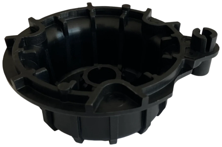
The quality and cost of a plastic part are largely determined at the design desk, before any mold is built. Plastic part design guidelines are the injection molding counterpart of the design for manufacturability (DFM) approach: the right wall thickness, adequate draft, balanced rib ratios and avoiding unnecessary undercuts directly affect defects such as sink marks and warpage as well as mold cost. In this article we summarize the key rules that product development and purchasing teams should check before moving on to the quotation stage.
Uniform Wall Thickness: The Foundation of All Rules
Molten plastic shrinks in volume as it cools in the mold. Because thick areas cool later than thin ones, they shrink at a different rate; the result is sink marks on the surface, internal voids and warpage. The first goal, therefore, is for the part to have a single, constant nominal wall thickness as far as possible.
- Changes in wall thickness should be gradual; the transition should be tapered so that its length is at least three times the thickness difference.
- Thick sections should be cored out rather than left solid, and the required stiffness should be provided by ribs.
- Material should always flow from thick to thin; the gate should be placed close to the thickest area where possible.
- Excessive wall thickness lengthens the cycle time. Since cooling time increases roughly with the square of the wall thickness, a 3 mm wall instead of 2 mm raises the cost per part noticeably.
Wall Thickness and Shrinkage by Material
The suitable wall thickness depends on the flowability of the material, the size of the part and the flow distance. The table below summarizes the general ranges commonly cited in the literature as a guide. For exact values, the technical data sheet of the resin to be used should be taken as the basis.
| Material | Typical wall thickness (mm) | Typical shrinkage (%) | Note |
|---|---|---|---|
| PP | 0.8 – 3.8 | 1.0 – 2.5 | Semi-crystalline; high shrinkage, suitable for flexible undercuts |
| ABS | 1.1 – 3.5 | 0.4 – 0.7 | Amorphous; good dimensional stability, relatively sensitive to sink marks |
| PC | 1.0 – 3.8 | 0.5 – 0.7 | Amorphous; sensitive to stress cracking at sharp corners |
| PA (unfilled) | 0.8 – 3.0 | 0.8 – 2.0 | Absorbs moisture; dimensions may change after molding |
| PA (glass-fiber reinforced) | 0.8 – 3.0 | 0.3 – 1.0 | Shrinkage differs with flow direction (anisotropic) |
Draft Angle and Radii
Draft (ejection) angle
For the part to come out of the mold without being forced, all surfaces parallel to the mold opening direction must have draft. As a general rule, 1°–2° is a safe starting point; 0.5° may be possible on polished surfaces. On textured (grain/EDM) surfaces the angle should be increased: a common practice is to add about 1° for every 0.025 mm of texture depth. When draft is insufficient, ejector marks, drag marks and deformation appear.
Corner radii
Sharp internal corners lead to both stress concentration and flow resistance. The internal corner radius should be at least half of the nominal wall thickness; the external radius should be the internal radius plus the wall thickness, so that a constant wall thickness is maintained at the corner as well. This approach significantly reduces the risk of breakage, especially in notch-sensitive materials such as PC.
Rib and Boss Design
Ribs
Ribs are the most efficient way to add stiffness without increasing wall thickness. However, a rib with the wrong proportions leaves a noticeable sink mark on the opposite surface.
- Rib thickness should be about 50–60% of the nominal wall thickness; on cosmetic surfaces it is safer to stay close to the lower limit.
- Rib height should not exceed three times the wall thickness; if more stiffness is needed, several short ribs should be preferred over a single tall one.
- The distance between ribs should be at least two wall thicknesses; otherwise the mold steel between them becomes thin and cooling becomes difficult.
- A radius of 0.25–0.5 times the wall thickness should be applied at the rib base, and a draft of 0.5°–1° on the side faces.
Boss (screw tower) design
Bosses used for screw and insert connections are a leading cause of sink marks and voids when they are designed thick and attached directly to the wall. Boss wall thickness should not exceed 60% of the nominal wall thickness, and the outside diameter should generally be about twice the hole diameter. Rather than connecting the boss to a side wall with a thick mass, it is better to connect it with supporting ribs (gussets) and to core out its base from the inside. For self-tapping screws, the hole diameter and boss dimensions should be determined according to the screw manufacturer's material-specific recommendations.
Undercuts and Their Effect on Mold Cost
Any feature that cannot be released directly in the mold opening direction (side holes, clip hooks, internal threads, reverse hooks) is an undercut and requires an additional mechanism in the mold. These mechanisms increase the mold's design and manufacturing time, maintenance needs and risk of failure.
- Slider (side core): Used for side holes and protrusions on the outer surface; it increases mold size and cost.
- Lifter (angled ejector): Used for small hooks and snaps on the inside; its range of movement must be planned into the design from the start.
- Rotating or collapsible core: Required for internal threads; among the most costly solutions.
- Forced ejection: With flexible materials such as PP and PE, shallow undercuts can be ejected without a mechanism; feasibility depends on the elongation capability of the material.
In most cases a small design change can eliminate the undercut entirely: for example, cutting a window beneath a clip hook and forming the feature with a shut-off between the mold halves. For this reason, undercuts should always be reviewed before mold design begins.
Managing Tolerances and Shrinkage
The tolerance achievable on plastic parts depends on the shrinkage of the material, the part size, the wall thickness distribution and process stability. It is generally difficult to hold tolerances as tight with high-shrinkage PP or PA as with low-shrinkage ABS or PC. The recommended approach in practice is as follows:
- Apply tight tolerances only to dimensions that are critical for assembly and function; for other dimensions, a general tolerance class (for example DIN ISO 20457) can be used as a reference.
- Keep in mind that dimensions that cross the mold parting line or depend on a slider will have wider tolerances.
- For glass-fiber reinforced materials, evaluate the shrinkage difference between flow direction and cross-flow direction, and the resulting warpage, in advance with mold flow analysis.
- Build the mold with a "steel-safe" approach on critical dimensions, so that corrections after the trial shot can be made by removing steel rather than adding it.
Conclusion
Constant wall thickness, adequate draft, correctly proportioned ribs and bosses and minimized undercuts mean a shorter cycle time, fewer trial rounds and a more economical mold. At Altınel Kalıp, we can review your part design with you for manufacturability and support you through mold making and the quotation process.