
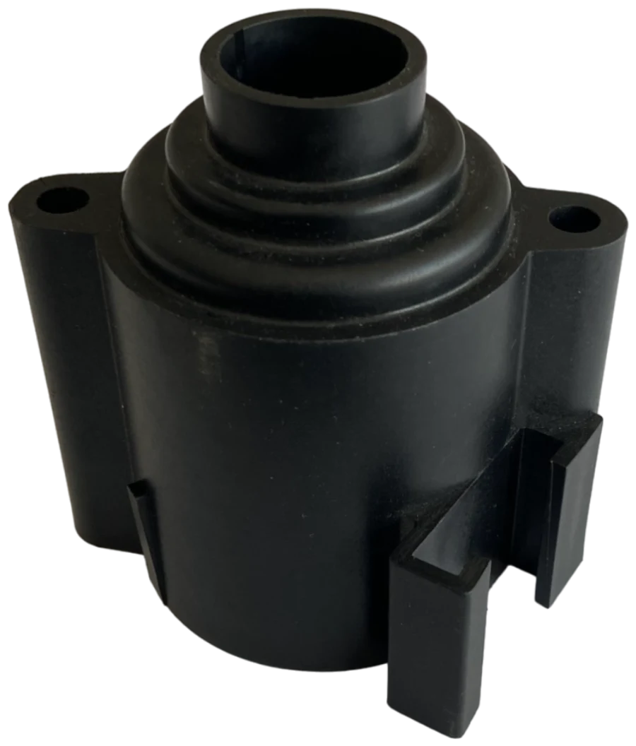
Among the issues that affect part quality most in series production are plastic injection molding defects. Flaws such as sink marks, flash, short shots or warpage do more than spoil the appearance: they cause assembly problems, raise scrap rates and push back delivery schedules. Most of these defects trace back to one of three sources: part design, mold design and process parameters. Interventions made without identifying the root cause often fix one defect only to create another.
A Root Cause Approach to Plastic Injection Molding Defects
When a defect appears, the first reflex is usually to adjust the machine settings: raise the pressure, increase the temperature, extend the cooling time. These changes may work in the short term, but they lengthen the cycle time and narrow the process window. For a lasting fix, the following questions need to be answered first:
- Does the defect appear on every shot, or only in certain cavities or at certain intervals?
- Where on the part does it occur: near the gate, at the end of fill, or in a thick section?
- Is there a time-related link to a material lot, drying conditions or a machine change?
- Is the temperature balanced between the two mold halves and between cavities?
The answers largely determine whether the problem should be solved on the process side or in the mold and part design.
The Most Common Injection Molding Defects and Their Causes
Sink Mark
These are shallow surface depressions that appear in thick sections and on the back side of ribs and bosses. As the plastic cools it shrinks in volume; if enough packing pressure cannot be transmitted before the core solidifies, the surface is pulled inward. Uneven wall thickness, a gate that freezes too early and a short packing time are the main causes.
Flash
Flash is a thin excess of material formed when molten plastic escapes through the parting line, around ejector pins or at core seating areas. Insufficient clamping force, excessive injection pressure, worn or damaged shut-off surfaces and overheating a low-viscosity material all lead to flash.
Short Shot
A short shot is a cavity that does not fill completely, usually seen at the end of the flow path, in thin walls or at rib tips. Typical causes are an insufficient shot size, low pressure or speed, a cold melt or mold, blocked venting and a flow path that is too long for the wall thickness.
Warpage
Warpage is the bending or twisting of a part after it leaves the mold. It originates from different areas of the part shrinking at different rates. Unbalanced mold cooling, differences in wall thickness and fiber orientation in glass-fiber reinforced materials are the most significant factors. Warpage is one of the hardest defects to correct through process settings.
Burn Mark
These are brown or black marks seen at the end of fill or in dead-end areas. Air trapped in the cavity is compressed during fast injection, overheats and burns the material, a phenomenon also known as the diesel effect. Poor venting, high injection speed and material degrading from sitting too long in the barrel are the main causes.
Flow Marks and Weld Line
Flow marks are wavy or ring-shaped surface irregularities around the gate. A weld line forms where two flow fronts meet around a hole or core. This area is not just a visual flaw; it is also a point where the part's mechanical strength drops. Low melt and mold temperature, slow injection and an unsuitable gate location are the main causes.
Air Bubbles and Voids
Voids are cavities that form inside thick sections. They share a mechanism with sink marks; the difference is that instead of the surface being pulled in, the outer skin hardens early and leaves a void inside. Moist material can also cause gas bubbles. For this reason, drying according to the manufacturer's recommendation is critical for hygroscopic materials such as PA, PC and PBT.
Defect – Cause – Solution Table
| Defect | Likely cause | Process solution | Mold / design solution |
|---|---|---|---|
| Sink mark | Thick section, insufficient packing | Increase packing pressure and time | Even out wall thickness, move the gate closer to the thick area, enlarge the gate cross-section |
| Flash | Insufficient clamping force, worn parting surface | Reduce pressure and melt temperature, check clamping force | Revise the parting line and shut-off fits |
| Short shot | Insufficient shot size or pressure, trapped air | Increase shot size, speed and temperature | Add venting, change the number or location of gates |
| Warpage | Unbalanced cooling, different shrinkage rates | Balance the temperatures of the mold halves, adjust cooling time | Rearrange cooling channels, balance wall thickness, add ribs |
| Burn mark | Trapped air, high injection speed | Gradually reduce speed toward the end of fill | Cut vents in the end-of-fill area |
| Weld line | Flow fronts meeting cold | Increase melt and mold temperature and injection speed | Change the gate location, add an overflow well |
| Air bubble | Moist material, thick section | Dry the material, increase packing pressure | Core out thick sections to thin them |
Process Adjustment or Mold Revision?
Cases that can be solved on the process side
If the defect is new, meaning the mold previously produced good parts, the process is the first place to look. A change of material lot, a dryer that is not working properly, a fault in the mold temperature controller or a machine change are common causes of this kind of defect. Short shots, light burn marks and moisture-related bubbles can mostly be eliminated by correcting parameters.
Cases that require mold and part design changes
If the defect has been present since the first trial shot and can only be controlled within a very narrow parameter range, the problem most likely lies in the design. Pronounced warpage, sink marks in thick sections, weld lines in critical areas and recurring flash fall into this group. In this case, instead of pushing the process window, the following measures should be considered:
- Reviewing the type, number and location of gates
- Rearranging cooling channels to suit the part geometry
- Adding vents at the end-of-fill areas
- Balancing wall thickness and correcting rib ratios
The Most Economical Way to Prevent Defects: The Design Stage
Every revision made after the mold steel has been machined costs both time and money. That is why it is both possible and necessary to anticipate most defects before the mold is built. Mold flow analysis shows the fill sequence, the areas where weld lines and air traps will form, the sink mark risk and the expected warpage tendency in a virtual environment. The gate location and cooling layout are determined based on these results.
The trial shots and sample approval process that follow reveal details the analysis could not predict. The sample approved through dimensional inspection and visual examination becomes the reference for series production. When the part designer, the mold maker and the production team work together at this stage, most of the problems that would appear in series production are eliminated from the start.
At Altınel Kalıp, we can review your part design for moldability and support you with mold making backed by flow analysis and with trial shots. If you would like to evaluate an existing defect or get a quote for a new project, you are welcome to contact us.