
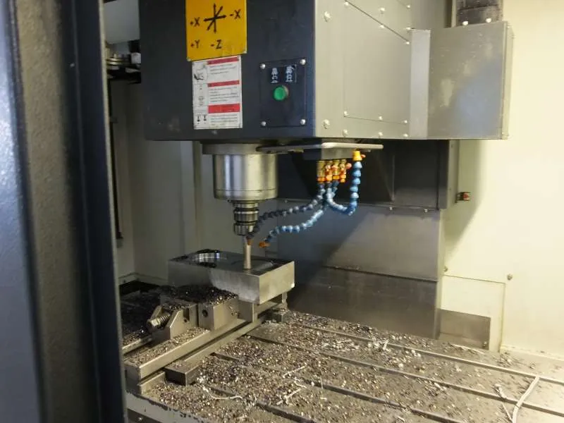
The quality of an injection mold depends largely on how the steel block is machined. CNC machining in mold making is the core manufacturing step that turns the three-dimensional model on the design screen into a real cavity and core with very tight tolerances. Dimensional consistency of the part, its surface appearance, the risk of flash at the parting line and even the cycle time are shaped by the decisions made at this stage. In this article we cover the process from roughing to finishing, the effect of the number of axes, tool and tool path selection, hardened steel machining and the points where EDM comes into play.
Roughing, Semi-Finishing and Finishing: A Three-Stage Approach
Mold steel is not brought to its final form in a single operation. Material removal is divided into three stages with different purposes:
- Roughing: The goal is to remove most of the material in the shortest possible time. Large-diameter cutters with indexable inserts and adaptive or trochoidal tool paths are typically used. A machining allowance of 0.3–1 mm is usually left on the surface.
- Semi-finishing: The stepped surface left by roughing is smoothed out and the allowance is evened out at every point. If this step is skipped, the finishing tool removes a lot of material in some places and very little in others, which results in tool deflection and dimensional errors.
- Finishing: The final geometry and surface are produced with small stepovers and ball-nose or bull-nose cutters. Dimensional accuracy and surface quality are determined here.
The principle of leaving an even allowance is the key to dimensional consistency, especially in molds with deep pockets and thin ribs. For this reason, the quality of the finish depends largely on the quality of the semi-finishing.
3-Axis and 5-Axis CNC: Which One and When?
3-axis machines are still the most economical solution for mold cavities with flat parting surfaces that are not very deep. In deep cavities, however, the tool has to be clamped with a long stick-out, which means vibration, deflection and poor surface finish.
In 5-axis machining, the workpiece or the spindle can tilt, so the tool can be clamped shorter and approach the surface at a suitable angle. With 3+2 (positional) machining, many mold components can be completed in a single setup; simultaneous 5-axis offers additional advantages on freeform surfaces and steep walls.
| Criterion | 3-Axis | 5-Axis (3+2 / simultaneous) |
|---|---|---|
| Deep pockets | Long tool, deflection risk | Short tool, more rigid cutting |
| Number of setups | Multiple setups may be needed | Mostly a single setup |
| Sloped surfaces and angled holes | Requires extra fixtures or EDM | Can be machined directly |
| Programming and cost | Simpler, more economical | Higher CAM and machine cost |
High-Speed Machining and Tool Path Strategy in CAM
High-speed machining (HSM) combines high spindle speed and feed rate with a low depth of cut. Because the force on the tool is lower, most of the heat is carried away with the chip, tool life is extended and thin walls can be machined without deforming. However, the efficiency of HSM depends more on the quality of the CAM program than on the machine.
Tool path selection
- Adaptive / trochoidal roughing: Keeps the tool's engagement angle constant and prevents sudden load spikes.
- Z-level (contour) finishing: Gives smooth and consistent results on steep walls.
- Parallel and spiral finishing: Leaves a uniform pattern on flat or gently sloped surfaces.
- Rest machining: Cleans up corners that a large tool could not reach, using a smaller tool.
Tool selection
Coated carbide cutters are generally preferred in mold machining. Bull-nose (corner radius) cutters are common for roughing and ball-nose cutters for finishing. The basic rule is to clamp the tool as short as possible and choose the largest diameter the geometry allows; as the length-to-diameter ratio grows, deflection increases rapidly. Collisions and holder contact should also be checked with CAM simulation before the program goes to the machine.
Hardened Steel Machining and the Role of EDM
In the traditional workflow, mold steel is machined in the soft condition, sent for heat treatment and then completed by grinding and EDM. Distortion during heat treatment, however, requires extra correction allowance and hand work. Today it is possible to mill steels directly up to about 50–60 HRC (hard milling). This way, distortion from heat treatment is removed at the finishing stage and the need for hand fitting is reduced.
Nevertheless, some geometries cannot be machined by milling or it is not economical to do so. In that case, sinker or wire EDM comes into play:
- Sharp internal corners and radii smaller than the tool radius
- Very narrow and deep rib slots
- Pockets with a high depth-to-width ratio
- Areas that require a special surface structure
- Precise ejector pin and core holes that must be cut by wire EDM
A good mold design plans the division of work between CNC and EDM from the start. For example, adding a small radius to internal corners in the part design can eliminate the need for an electrode and reduce both time and cost. When needed, the electrodes themselves are also machined from graphite or copper on CNC machines.
Measurement, Verification and Surface Quality
Once machining is complete, the part is not assembled before it has been measured. On-machine probing checks the zero point and critical dimensions during the process; finished parts are then compared against the CAD model using a coordinate measuring machine (CMM) or optical scanning. This verification is critical for catching dimensional differences between cavities early, especially in multi-cavity molds.
Surface quality is directly related to the finishing stepover, tool wear and machine dynamics. The closer CNC machining gets to the target roughness, the shorter the subsequent polishing time. Polishing is unavoidable on transparent parts that require a mirror finish; on surfaces that will be textured, a uniform finishing pattern helps the texture come out even.
| Problem | Likely cause | Solution |
|---|---|---|
| Wavy surface, chatter marks | Long tool stick-out, high cutting force | Shorter clamping, 5-axis tilting, lower depth of cut |
| Dimensional deviation | Uneven finishing allowance, tool wear | Semi-finishing, tool length measurement, rest machining |
| Step marks in corners | Tool path transitions, abrupt changes of direction | Smoothed tool paths, suitable lead-in and lead-out moves |
Conclusion: Proper Planning, Shorter Mold Lead Time
CNC machining in mold making succeeds not through machine power alone, but through the right sequence of operations, suitable axis selection, a well-designed CAM strategy and systematic measurement. When these steps are considered together at the part design stage, revisions after the trial shot decrease and the mold is ready for sample approval in less time.
When you need a design review, mold making or a quote for your part, you can contact the Altınel Kalıp team.