
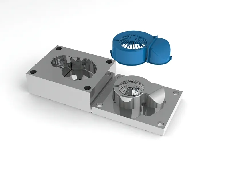
Two molds machined from the same steel on the same machines are designed with quite different priorities when one is made for an automotive clip and the other for a chair part. Designing injection molds by industry means taking the environment the part will work in, the standards it has to meet and the production volume into account in the very first design meeting. In this article we summarize how expectations of the mold change across the automotive, home appliance, electrical-electronics, irrigation and filtration, and furniture and household products sectors.
Comparing Mold Requirements by Industry
The table below gives a general overview of the materials that stand out in each industry and the points that mold design focuses on. Final decisions are always made according to the part geometry and the customer specification.
| Industry | Typical materials | Critical requirements | Mold focus |
|---|---|---|---|
| Automotive | PP-T20, PA6-GF30, PC/ABS, POM | Tight tolerances, clip strength, cosmetic surface quality | Warpage control, runner balance, texture and surface, documented sample approval |
| Home appliances | PP, ABS, HIPS, PC | Large, thin-walled parts, glossy surfaces | Flow analysis, hot runner, uniform cooling, mold rigidity, polishing |
| Electrical-electronics | Flame-retardant PC, PA66-GF, PBT, ABS | Flame rating, flatness, screw bosses | Gas venting, corrosion-resistant steel, boss and core cooling |
| Irrigation and filtration | PP, POM, PA-GF, aluminium alloys | Pressure resistance, sealing surfaces | Weld line management, precision surfaces, aluminium die casting molds |
| Furniture and household products | PP, PE, PA-GF, ABS | High volume, low unit cost | Multi-cavity mold, short cycle time, wear resistance |
Automotive: Tight Tolerances and Documented Sample Approval
Automotive parts are usually assembled with other parts and are exposed to vibration, temperature changes and chemicals throughout the life of the vehicle. For this reason, the priority in mold design is dimensional stability and repeatability.
Clips and snap-fit connections
Clips must flex during assembly and still hold once seated. In the mold, these areas often require a core, slider or angled lifter. The gate location should be determined with flow analysis so that weld lines do not fall at the clip root; otherwise the risk of breakage during assembly increases.
Filled materials and warpage
Talc-filled materials such as PP-T20 and glass-fiber reinforced materials such as PA6-GF30 provide stiffness, but because of fiber orientation they shrink differently along and across the flow direction. This leads to warpage. In mold design, the gate location, the layout of the cooling channels and, if necessary, dimensional correction allowances are planned from the start. Because glass fiber is abrasive, hardened steel or replaceable inserts are preferred in the gate areas.
Cosmetic surfaces and sample approval
On interior trim parts, texture quality, flow lines and sink marks are direct grounds for rejection. At the sample stage, a PPAP-like process documents the dimensional report, material certificate and process parameters. The mold is expected to produce the same part in every run using the approved process.
Home Appliances: Large, Thin-Walled and Glossy Parts
Washing machine panels, refrigerator interior parts and vacuum cleaner housings are designed with thin walls despite their large surface area. As the ratio of flow length to wall thickness rises, a high injection pressure is needed. This in turn makes it necessary to size the mold plates and support pillars rigidly enough to prevent flash.
Large parts commonly use multi-drop hot runners. With sequential valve gate control, weld lines can be moved to areas where they are not visible. On glossy surfaces, the polishability of the steel, the polishing quality and the mold surface temperature are decisive; where necessary, heating-cooling (variotherm) techniques are used to reduce weld lines and flow marks. For a clean appearance on wide panels, cooling must be balanced across the entire surface.
Electrical-Electronics: Flame-Retardant Material, Flatness and Screw Bosses
For sockets, fuse boxes, chargers and electronic enclosures, a specific flame rating is usually required of the material. Materials with flame-retardant additives have a narrow processing window and, at high temperatures, can leave deposits on the mold surface and generate corrosive gases. For this reason:
- Gas vents must be cut at sufficient depth and in the right positions.
- Corrosion-resistant mold steel should be selected, or a surface coating should be considered.
- Mold maintenance and cleaning intervals should be added to the process plan.
For cover and housing parts to fit each other and the electronic board exactly, flatness is a critical dimension. Symmetric cooling, balanced wall thickness and correct rib design are decisive here. On screw bosses, the wall thickness around the boss should be set so that it does not cause sink marks, and thin core pins should be cooled adequately. Since a weld line on a boss can cause cracking during screw driving, the gate location is chosen accordingly.
Irrigation and Filtration: Pressure Resistance and Sealing
Filter housings, valve parts and fittings work under constant internal pressure. Because weld lines in pressurized areas are the weakest point of the part, the mold is designed to direct these lines toward low-stress areas. For threaded parts, mold solutions with rotating cores (unscrewing) or collapsible cores come into play.
O-ring grooves and gasket surfaces require that the parting line and ejector marks do not fall on these surfaces. Even the smallest flash can cause a part to be rejected in a leak test.
For metal filter housings and high-pressure parts, aluminium injection (pressure die casting) molds are used. Here the focus is on porosity control, overflow wells and venting design, and on the resistance of hot work tool steel to thermal fatigue. Sealing surfaces are usually machined by CNC after casting, so a suitable machining allowance must be left in the mold.
Furniture and Household Products: Multi-Cavity Molds and Cycle Time
For parts such as furniture accessories, legs, handles and kitchenware, annual volumes are high and unit price pressure is strong. In this sector the factor that determines part cost most is cycle time, and most of the cycle time is spent on cooling.
- Multi-cavity mold: As the number of cavities increases, a balanced runner or hot runner system is essential so that all cavities fill at the same time and equally.
- Efficient cooling: Placing channels close to the mold surface and in a balanced layout directly shortens the cycle.
- Durability: In molds designed for millions of shots, hardened steel and replaceable wear components reduce cost over the long term.
- Automation compatibility: Robotic part removal and in-mold runner separation reduce dependence on operators.
Information to Share Before Requesting a Quote
Whatever your industry, the mold maker needs the following information to design correctly:
- Annual production quantity and expected mold life
- Material type and the approved supplier list, if any
- Critical dimensions, tolerances and assembly method
- Expectations for cosmetic surfaces, texture and color
- Tests to be applied and industry standards
The earlier this information is settled, the fewer surprises there will be in the flow analysis and design revisions.
At Altınel Kalıp, we can evaluate your part with you at the design stage according to the requirements of your industry, build your plastic or aluminium injection mold and carry the process through to trial shots and sample approval. You can share your technical drawing or 3D model to request a quote.